| Version 32 (modified by kubel, 13 years ago) (diff) |
|---|
Preparation of CAF slide from vector graphics
Page contents:
Contour slide
In our work-flow we introduced a stage of contour slides - vector graphic in SVG format (for detailed description see Majka et al 2011) that simplifies necessary corrections, manual preparation of structures' outlines from histology results and further improvements of slide details.
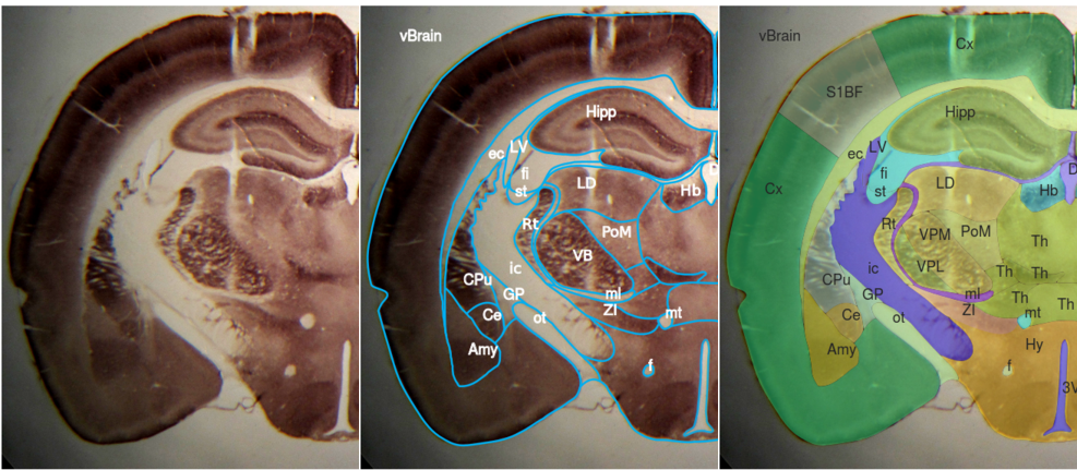
FIGURE 1.
Left: Coronal slice of a rat brain around 3 mm behind Bregma stained for Cytochrome Oxidase. Histological verification of the electrodes' location after chronic local field potentials (LFP) recording from the thalamic somatosensory nuclei. Middle: Initial stage of manual preparation of a countour slide. Main structures outlines drawn over the histology slice (line thickness increased for better visibility) and structure labels placed over well recognized regions. Right: Histological slice visible through translucent final CAF slide.
Typical problems and their solutions
Most commonly available 2D atlases were not designed to be used as sources for 3D models generation. Precision of contour definitions and label placement is sufficient for standard use, but not always for the automatic reconstruction process. For example, in some published atlases one may find a number of deliberate simplifications e.g. labels are omitted because names of some areas are considered obvious or labels are literally too large to put them inside the represented area. Such omissions have to be fixed in order to get a correct 3D reconstruction, indeed for any systematic computer processing.
Manually prepared contour slides - including our example presented here - also can contain errors requiring corrections.
Non-interactive error correction
The vector parser tries to automatically deal with troublesome situations. However, if it is unable to correct a problem automatically, the program will notify the user and save all the important information about the case as a thumbnail image including name of the problematic label and its location. These data help the user to solve the problem manually by removing ambiguities from contour slides. Below we discuss and illustrate common inconveniences and our strategies for fixing them.
Labels
Unlabelled areas
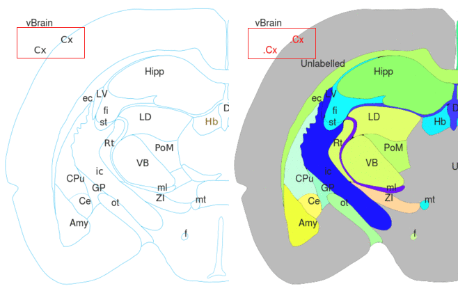
A problem we encountered during tracing was the lack of labels attributed to some areas. This can happen when "obvious" names are omitted in commercial atlases; when user does not recognize the area in histological slice (see example in figure 5), but also when additional area is erroneously defined by accidental line crossing (see figure 2 below).
3dBAR vector parser automatically detects such unlabeled regions by comparing the sum of traced paths with the total area of the Brain structure. The parser locates all contiguous unlabelled regions consisting of more than a given number of pixels and traces them. The resulting structures are called Unlabelled and may be indexed and reconstructed similarly to the regular structures.
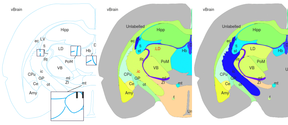
FIGURE 2.
Left: Red blocks mark regions where irregular neighboring lines touch each other creating small closed areas. Middle: Small areas were detected by the parser, traced and marked as Unlabelled. Right: Adjusting the threshold number of pixels that should be traces by parser excluded incorrectly recognized tiny structures.
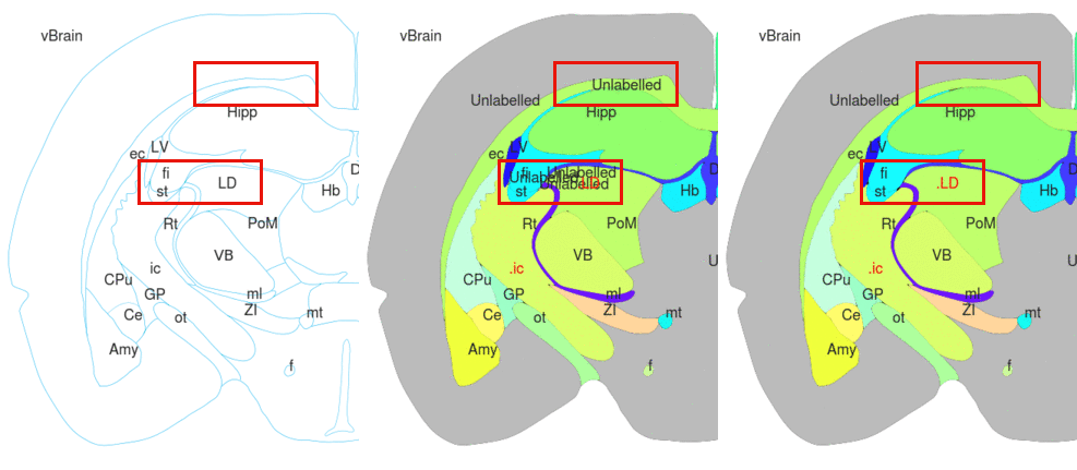
Duplicated labels within a single contour
Another common difficulty is an absence of borders drawn within an outline containing multiple labels.
This can be a consequence of improper drawing but often
simply follows from lack of sharp transitions between structures.
When the parser detects two or more overlapping regions that were
created based on different labels such labels are changed to
spot labels in the CAF slide and a notification is logged. Neither
path is removed as there is no way to determine which one should be
discarded and which should be kept. After tracing, the user is notified
about ambiguous delineation and should review the slide in question
and correct it.
In the CAF slide on the right of Figure 2 above we can see two labels (ic, Rt) located within one region. One of them was changed by parser to spot label (.ic). This particular example resulted from improper drawing and a gap existing in the border between internal capsule (ic) and reticular nucleus of the thalamus (Rt). The parser treated areas connected by the gap as one structure (leaking of the structure, see below).
Incorrect label placement
Error correction procedure also looks for labels displaced outside the brain outline or labels anchored directly above contours.
The latter may happen when a structure is defined as a thin
strip between other structures. Since tracing contours themselves is not allowed, such incidents are recorded and a thumbnail image is generated allowing user to examine
and correct the error.
Tracing of a region corresponding to the incorrectly placed label is skipped but in general tracing is not interrupted as the whole procedure works non-interactively.
Leaking structures and gap filling algorithm
The most common drawing defect is gaps in structure outlines. It frequently happens when two contour lines, which should touch are drawn so that they leave a little space in between. Such an arrangement may not be visible in a printed atlas but it greatly disturbs the tracing process where every pixel may influence the results. In this case, the structure being traced overtakes the space of its neighbour through the broken contour which we call leaking of the structure (see inserts in Figure 4 below ).
It is handled by a heuristic gap filling algorithm (detailed description). The main idea behind this algorithm is to expand the contours by applying a dilation filter ( Gonzalez2008) until the boundary closes. If a very accurate reconstruction is required, the best policy is to prepare a precise contour slide so there is no need to apply gap filling. For the atlases we tested, the gap filling algorithm performed well, the reconstructed structures were adequate and the gains in time were tremendous as compared with manual cleaning.
Slice details improvement
Individual substructures singled out
...by simple line drawing and new regions labeling. Unrecognized areas can be attributed to the structures from the upper hierarchy level.
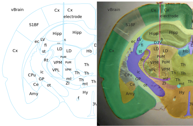
FIGURE 5.
Left: New lines and appropriate labels (blinking) were added to the contour slide 1) to show primary somatosensory representation of big facial whiskers ("barrel field", S1BF) in the cerebral cortex (Cx); and 2) to divide ventrobasal complex (VB) into ventral posteromedial (VPM) and ventral posterolateral (VPL) nuclei. Unrecognized thalamic nuclei, which were not labeled with their specific names, are labeled with "Th" so they all will be included in the final reconstruction of the thalamus. Right: Updated CAF slide.
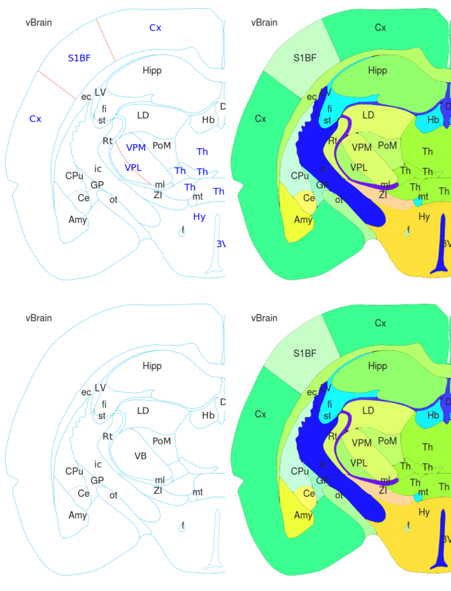
Additional elements apart anatomical data included in CAF slide
In our example we include in the slide an outline of the electrode. Spaces occupied by lesions or injected dyes can be also added to atlas elements.
List of used abbreviations
- vBrain
- ec
- LV
- fi
- Hipp
- LD
- Rt
- ic
- CPu
- Ce
- Amy
- ot
- ZI
- mt
- ml
- VB
- PoM
- LD
- Hb
- D3V
- 3V
- Cx
- S1BF
Attachments
-
006__final_comparison.png
 (1.4 MB) -
added by pmajka 13 years ago.
-
007__final_electrode.png
 (828.2 KB) -
added by pmajka 13 years ago.
-
0041_new_edges_animated.gif
 (91.6 KB) -
added by pmajka 13 years ago.
-
001__unlabelled_annotated.gif
 (59.1 KB) -
added by pmajka 13 years ago.
-
003__invalid_labels_annotated.gif
 (39.7 KB) -
added by pmajka 13 years ago.
-
002__gapfill_annotated.gif
 (62.7 KB) -
added by pmajka 13 years ago.

