Detailed description of gap-filling algorithm
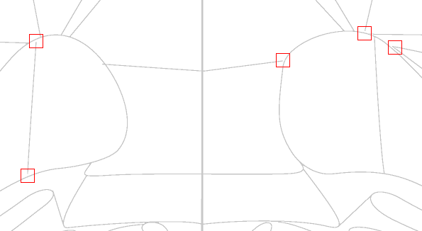
The most common defect encountered in digital (e.g. PDF) versions of published atlases are gaps in structures' outlines. It commonly happens when two contour lines which should touch are drawn so that they leave a little space in between. Such an arrangement may not be visible in a printed atlas but it greatly disturbs tracing process where every pixel may influence the results. In this case the structure being traced overtakes the space of its neighbour through the broken contour which we call leaking of the structure (see figure below).
Figure 1: Examples of gaps in structures contours.
Fragment of rasterized contour slide based on Paxinos and Franklin The Mouse Brain In Stereotaxic Coordinates, third edition.
Leaking structures are handled in 3dBAR by a gap filling algorithm, an extension of the basic tracing procedure. The main idea behind this algorithm is to expand the contours by applying dilation filter until the boundary closes.
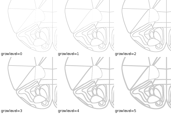
The algorithm requires a single input parameter - MaxGrowLevel - describing the maximum size of the gaps that may be closed during tracing of a particular area, and works as follows: First, the initial bitmap is duplicated. Dilation filter is applied to the copy and the result is also cached. This procedure is repeated MaxGrowLevel times. Each application of the dilation filter causes the boundaries of the structures to grow approximately 1 pixel in diameter. As a result, MaxGrowLevel+1 bitmaps are cached with the first being the rasterized version of the original contour slide (see Figure 2 below).
Figure 2: Consecutive application of dilation filter to a rasterized contour slide.
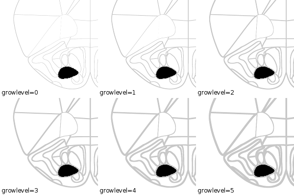
Structure areas on each cached bitmap are flood-filled and then dilated the same number of times as the boundaries were grown to ensure that the area of the resulting path stays unbiased. If it remains stable or slightly lowers (less than 2% in our implementation) at consecutive stages of the algorithm it means that most probably the boundaries of the structure in question do not have any gaps (see Fig. 3).
Figure 3: Structure without gaps does not express significant changes of its area across different stages of the algorithm (see table below).
growlevel area of the structure in pixels 0 51124 1 51124 2 51124 3 51124 4 51124 5 51112
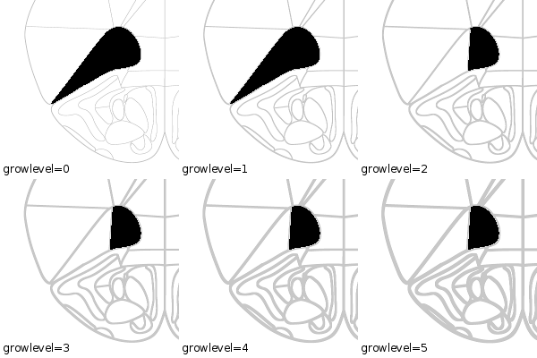
If the reduction of flooded area at certain stage of filter application is greater than a defined threshold (15-20% in our implementation), it means that a gap in the boundary must have been closed (see Figure 4 below). After finding the optimal number of border expansions (denoted by growlevel) the corresponding bitmap is passed to PoTrace.
Figure 4: Structure with gap(s) in it's contour expresses significant changes of its area. We can see sudden drop of the number of pixels at certain stage (here at growlevel=2) of the algorithm application when the gap is closed (see table below).
growlevel area of the structure in pixels 0 196243 1 196232 2 84384 3 84331 4 84331 5 84309
The gap filling algorithm is applied individually for each seed label thus different regions may be processed with different values of growlevel. Information about which growlevel was used to trace a particular path is stored in its attributes.
Preconfiguration
The gap filling algorithm may be preconfigured during the preparation of a contour slide. The preconfiguration is carried out by assigning bar:growlevel attribute to the label used as the seed for tracing. The value of this attribute should be an integer between -1 and MaxGrowLevel. Assigning -1 means that growlevel is undefined and has to be selected automatically, 0 means that gap filling should not be used for this particular label. Other values denote the number of dilation filter applications.
Algorithm efficacy and limitations
The table below summarizes results of the gap filling algorithm applied to 47 paths from 13th coronal section (2.1mm ant. from bregma) from Paxinos and Franklin The Mouse Brain In Stereotaxic Coordinates, third edition.
| optimal grow level | number of paths |
|---|---|
| 0 | 28 |
| 1 | 9 |
| 2 | 10 |
The performance of the algorithm depends on the initial size of the structure and on the bitmap resolution. Intensive use of this algorithm may distort or even erase some (particularly narrow) structures. There is no specific mechanism implemented against such behavior. If a very accurate reconstruction is required, the best policy is to carefully prepare contour slides adjusting stroke width and slice resterization resolution so there is no need to apply gap filling.
Attachments
-
debug_100_99_vBrain_step_0.gif
 (8.1 KB) -
added by pmajka 14 years ago.
-
debug_460_461_VO_step_0-anim.gif
 (46.1 KB) -
added by pmajka 14 years ago.
-
debug_460_461_VO_step_0-anim-AOP.gif
 (46.0 KB) -
added by pmajka 14 years ago.
-
debug_460_461_VO_step_0-anim-VO.gif
 (46.0 KB) -
added by pmajka 14 years ago.


